|
|||||||||||||||
FreeRTOS for the Renesas RL78 MCU
|
|||||||||||||||


|
|
| Renesas RL78 promotion and starter kits | |
This page documents an application that demonstrates the use of FreeRTOS on
a Renesas RL78 16-bit microcontroller.
The demo includes five separate build configurations, one for each of the following device evaluation boards:
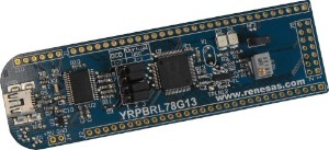
- YRPBRL78G13 - Renesas RL78/G13 promotion board
- YRDKRL78G14 - Renesas RL78/G14 development board
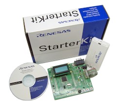
- RSKRL78G1C - Renesas RL78/G1C starter kit
- RSKRL78L13 - Renesas RL78/L13 starter kit
- RL78/G1A TB - Renesas RL78/G1A target board
Note: The project described on this page requires IAR Embedded Workbench for the RL78 (EWRL78) version 1.30.2 or higher. A free evaluation edition of EWRL78 is available for download from the IAR web site.
If this project fails to build then it is likely the version of IAR Embedded Workbench being used is too old. Opening an IAR project in a version of EWRL78 that is older than the version used to create the project will often (silently) corrupt the project file, necessitating that a clean copy of the project is restored from the FreeRTOS zip file download before proceeding with an updated compiler.
IMPORTANT! Notes on using the Renesas RL78 RTOS port
Please read all the following points before using this RTOS port.See also the FAQ My application does not run, what could be wrong?
Source Code Organization
The FreeRTOS download contains the source code for all the FreeRTOS ports, so contains many more files than used by this demo.See the Source Code Organization section for a description of the downloaded files and information on creating a new project.
The IAR Embedded Workbench workspace for the Renesas RL78 project is called RTOSDemo.eww, and is located in the FreeRTOS\Demo\RL78_multiple_IAR directory.
The Demo Application
Demo application hardware setup
The demo application makes use of an LED that is mounted directly onto each of the supported hardware platforms. No hardware setup is required.
Functionality
mainCREATE_SIMPLE_BLINKY_DEMO_ONLY is #define'ed in main.c. If mainCREATE_SIMPLE_BLINKY_DEMO_ONLY is set to 1 then main() will call main_blinky(), which creates a simple 'blinky' style demo. If mainCREATE_SIMPLE_BLINKY_DEMO_ONLY is set to 0 then main() will call main_full() which creates a more comprehensive demo.
Functionality when mainCREATE_SIMPLE_BLINKY_DEMO_ONLY is set to 1
main_blinky() creates one queue, and two tasks before starting the RTOS scheduler.-
The Queue Send Task:
The queue send task is implemented by the prvQueueSendTask() function in main_blinky.c.
prvQueueSendTask() sits in a loop that causes it to repeatedly block for 200 milliseconds, before sending the value 100 to the queue that was created within main_blinky(). Once the value is sent, the task loops back around to block for another 200 milliseconds, and so on.
-
The Queue Receive Task:
The queue receive task is implemented by the prvQueueReceiveTask() function in main_blinky.c.
prvQueueReceiveTask() sits in a loop where it repeatedly blocks on attempts to read data from the queue that was created within main_blinky(), toggling an LED each time the value 100 is received.
The queue receive task will only leave the Blocked state when the queue send task writes to the queue. As the queue send task writes to the queue every 200 milliseconds, the queue receive task leaves the Blocked state and toggles the LED every 200 milliseconds.
Functionality when mainCREATE_SIMPLE_BLINKY_DEMO_ONLY is set to 0
main_full() creates 13 tasks, 4 queues, and 2 software timers. Many of the tasks are from the set of standard demo tasks that are used with all the RTOS demos, and are documented on the FreeRTOS.org website.The following tasks and timers are created in addition to the standard demo tasks.
These fill the registers with known values, then check that each register still contains its expected value. Each task uses a different set of values. The reg test tasks execute with a very low priority, so get preempted very frequently. A register containing an unexpected value is indicative of an error in the context switching mechanism.
The demo software timer callback function does nothing more than increment a variable. The period of the demo timer is set relative to the period of the check timer (described below). This allows the check timer to know how many times the demo timer callback function should execute between each execution of the check timer callback function. The variable incremented in the demo timer callback function is used to determine how many times the callback function has executed.
The check software timer period is initially set to three seconds. The check timer callback function checks that all the standard demo tasks, the reg test tasks, and the demo timer are not only still executing, but are executing without reporting any errors. If the check timer discovers that a task or timer has stalled, or reported an error, then it changes its own period from the initial three seconds, to just 200ms.
The check timer callback function also toggles an LED each time it is called. This provides a visual indication of the system status: If the LED toggles every three seconds, then no issues have been discovered. If the LED toggles every 200ms, then an issue has been discovered with at least one task.
Building the demo application
- Open the FreeRTOS\Demo\RL78_multiple_IAR\RTOSDemo.eww workspace from within IAR's Embedded Workbench IDE.
- Use the drop down list at the top of the Workspace window (in the open project) to select the build configuration that is correct for the target hardware being used.
- Press F7 to build the project. The project should build without any errors or warnings being generated (when the far memory model is used).
Programming the microcontroller and debugging
- Ensure the target board is connected to the host computer as appropriate. Some development platforms include a built in J-Link interface and only require a USB cable. Other platforms require a Renesas E1 debug interface.
- Select "Download and Debug" from the Embedded Workbench "Project" menu. IAR may prompt you to configure the debugger interface, after which there will be a short delay while the flash memory is programmed before the debugger breaks on entry to the main() function.
Configuration and Usage Details
RTOS port specific configuration
Configuration items specific to this demo are contained in FreeRTOS\Demo\RL78_multiple_IAR\FreeRTOSConfig.h. The constants defined in this file can be edited to suit your application.Each port #defines 'BaseType_t' to equal the most efficient data type for that processor. This port defines BaseType_t to be of type short.
Note that vPortEndScheduler() has not been implemented.
Memory models
The FreeRTOS port will automatically switch between the near and far memory models, depending on the settings in the IAR project options. The port has been tested with two memory model combinations, which are:
- The data and code models both set to near.
- The data and code models both set to far.
Writing interrupt service routines
Interrupt service routines that cannot cause a context switch have no special requirements and can be written as described by the IAR compiler documentation.Often you will require an interrupt service routine to cause a context switch. For example a serial port character being received may unblock a high priority task that was blocked waiting for the character to arrive. If the unblocked task has a higher priority than the current task (the task that was interrupted by the ISR), then the ISR should return directly to the unblocked task. The use of the IAR tools necessitates such interrupt service routines are entered using an assembly file wrapper. An example is provided below, and another example is provided in main.c. First the assembly file wrapper.
; ISR_Support.h defines the portSAVE_CONTEXT and portRESTORE_CONTEXT
; macros.
#include "ISR_Support.h"

    ; The wrapped implemented in the assembly file.
    PUBLIC    vISRWrapper

    ; The portion of the handler that is implemented in an external C file.
    EXTERN    vISRHandler

    ; Ensure the code segment is used.
    RSEG CODE:CODE

; The wrapper is the interrupt entry point.
vISRWrapper:

    ; The ISR must start with a call to the portSAVE_CONTEXT() macro to save
    ; the context of the currently running task.
    portSAVE_CONTEXT

    ; Once the context is saved the C portion of the handler can be called.
    ; This is where the interrupting peripheral is actually serviced.
    call vISRHandler

    ; Finally the ISR must end with a call to portRESTORE_CONTEXT() followed by
    ; a reti instruction to return from the interrupt to whichever task is
    ; now the task selected to run (which may be different to the task that
    ; was running before the interrupt started).
    portRESTORE_CONTEXT
    reti


    ; The interrupt handler can be installed into the vector table in the same
    ;assembly file.

    ; Ensure the vector table segment is used.
    COMMON INTVEC:CODE:ROOT(1)

    ; Place a pointer to the asm wrapper at the correct index into the vector
    ; table.  Note 56 is used is purely as an example.  The correct vector
    ; number for the interrupt being installed must be used.
    ORG 56
    DW vISRWrapper
The C portion of the interrupt handler is just a standard C function.
/* This standard C function is called from the assembly wrapper above. */
void vISRHandler( void )
{
short sHigherPriorityTaskWoken = pdFALSE;

    /* Handler code goes here, for purposes of demonstration, assume
    at some point the hander calls xSemaphoreGiveFromISR().*/
    xSemaphoreGiveFromISR( xSemaphore, &sHigherPriorityTaskWoken );

    /* If giving the semaphore unblocked a task, and the unblocked task has a
    priority that is higher than the currently running task, then
    sHigherPriorityTaskWoken will have been set to pdTRUE.  Passing a pdTRUE
    value to portYIELD_FROM_ISR() will cause this interrupt to return directly
    to the higher priority unblocked task. */
    portYIELD_FROM_ISR( sHigherPriorityTaskWoken );
}
Resources used by the RTOS kernel
By default the RTOS kernel uses the interval timer to generate the RTOS tick. The application writer can define configSETUP_TICK_INTERRUPT() (in FreeRTOSConfig.h) such that their own tick interrupt configuration is used in place of the default. For example, if the application writer creates a function called MyTimerSetup() that configures an alternative timer to generate an interrupt at the required frequency, then adding the following code to FreeRTOSConfig.h will cause MyTimerSetup() to be called in place of the default timer configuration:#define configSETUP_TICK_INTERRUPT() MyTimerSetup()NOTE: vPortTickISR() must be installed as the handler for which ever interrupt is used to generate the RTOS tick.
The RTOS kernel also requires exclusive use of the BRK software interrupt instruction.
Compiler options
As with all the ports, it is essential that the correct compiler options are used. The best way to ensure this is to base your application on the provided demo application files.Memory allocation
Source\Portable\MemMang\heap_1.c is included in the demo application project to provide the memory allocation required by the RTOS kernel. Please refer to the Memory Management section of the API documentation for full information.
NXP tweet showing LPC5500 (ARMv8-M Cortex-M33) running FreeRTOS.
Meet Richard Barry and learn about running FreeRTOS on RISC-V at FOSDEM 2019
Version 10.1.1 of the FreeRTOS kernel is available for immediate download. MIT licensed.
View a recording of the "OTA Update Security and Reliability" webinar, presented by TI and AWS.
FreeRTOS and other embedded software careers at AWS.

![]()


![]()