FreeRTOS Spansion (was Fujitsu) 16FX demo
[RTOS Ports]
This page presents the FreeRTOS demo application for the Spansion MB96340 series RTOS port.
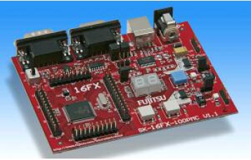
The demo is pre-configured to run on the SK-16FX-EUROScope starterkit from Spansion. The
Softune compiler and IDE,
and the EUROScope Lite debugger are used - both of which are included within the starterkit.
IMPORTANT! Notes on using the Spansion (was Fujitsu) 16FX Demo
Please read all the following points before using this RTOS port.
- Source Code Organisation
- The Demo Application
- RTOS Configuration and Usage Details
See also the FAQ My application does not run, what could be wrong?
Source Code Organisation
The Softune workspace for the 16FX demo is called 96340_FreeRTOS_96348hs.wsp and can be located in the Demo/MB96340_Softune directory.
The FreeRTOS zip file download contains files for all the ports and demo application projects. It therefore contains many more files
than used by this demo. See the Source Code Organization section for a description of the
downloaded files and information on creating a new project.
The Demo Application
Demo application setup
The demo application includes an interrupt driven UART test where one task transmits characters that are then received by another task. For correct operation
of this functionality a loopback connector must be fitted to the X4 connector of the SK-16FX-EUROScope board (pins 2 and 3
must be connected together on the 9Way connector).
You can power the starter kit through its USB port, and use the same USB port as a virtual COM port. You will be prompted to install USB drivers when connecting
the starter kit via a USB cable for the first time. The required drivers are provided on the starter kit CD.
No further specific hardware setup is required.
Building the application, programming the Flash memory, and debugging are all performed using separate programs - these are Softune itself, the Spansion Flash MCU programmer,
and EUROScope lite respectively. Installation executables for all three are provided on the starter kit CD. Softune and EUROScope both require that you register the software
and obtain a license file - this process is fast and free of charge.
Building the demo application
- Open the Demo/MB96340_Softune/96340_FreeRTOS_96348hs.wsp workspace from within the Softune IDE.
- Select 'Build' from the IDE Project menu - the demo application should compile with no errors or warnings, although the linking phase will output warning regarding the lack
of debug information in the Softune libraries. The linker warning are unavoidable and can be ignored.
Programming the microcontroller Flash memory
- Connect the starter kit to your host PC using a USB cable.
- Start the Spansion Flash MCU programming utility.
- Ensure the correct MCU and crystal frequency are selected - highlighted in red in the image below.
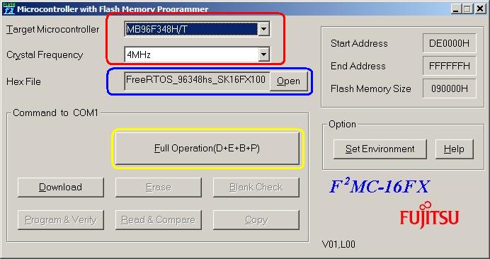 The Spansion Flash MCU programming utility The Spansion Flash MCU programming utility
- Use the 'Open' button (highlighted in blue in the image above) to select the built file Demo/MB96340_Softune/FreeRTOS_96348hs_SK16FX100PMC/STANDALONE/ABS/
FreeRTOS_96348hs_SK16FX100PMC.mhx
- On the Flash programming utility, click 'Set Environment' and ensure that the (virtual) COM port assigned to the USB connection is selected. The Windows Device Manager can be used to
check which port was assigned to the USB connection:
- Select 'System' from within the Windows Control Panel. System Properties dialogue will open.
- Select the 'Hardware' tab of the System Properties dialogue, then click the 'Device Manager' button (highlighted in red in the image below). The Device Manager window will open.
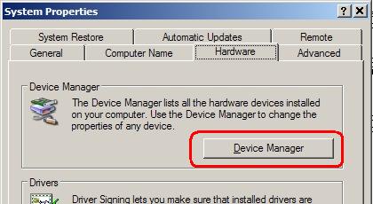 Opening the Device Manager Opening the Device Manager
- Expand the 'Ports (Com and LPT) node within the Device Manager to reveal the port assigned to the Spansion connection (COM4 in the case depicted below).
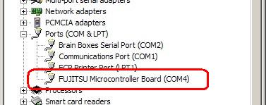 Viewing the port assigned to the Spansion USB connection Viewing the port assigned to the Spansion USB connection
- On the starter kit board, ensure switch S1 is in the programming position (toward the D connectors), then press the blue button to reset the MCU.
- Finally, click the 'Full Operation' button within the Flash programming utility (highlighted in yellow in the image above). Programming the flash should not take more than approximately
20 seconds.
- To start the program executing, move S1 back to the Run position before pressing the blue button (on the starter kit) once again. Make sure ensure the
loopback connector is on X4 (as described under "Demo Application Setup" above) before resetting the board.
Starting a debug session
- Following on from the instructions to program the MCU flash - leave the RS232 (or USB virtual COM port) cable in place, and the switch SW1 in the run position.
- Ensure the Flash programming utility is no longer running as it will prevent the debugger from accessing the COM port.
- Start the EUROScope debugging software.
- Select 'Open Application' from the EUROScope file menu, then navigate to and open the Demo/MB96340_Softune/FreeRTOS_96348hs_SK16FX100PMC/STANDALONE/ABS/
FreeRTOS_96348hs_SK16FX100PMC.abs
file. Note this time we have opened the .abs file, whereas within the Flash programming utility we opened the .mhx file.
- Select 'Select Target Connection' from the Euroscope 'Preferences' menu, then ensure "Fujitsu 16FXBootROM (RS232)" is selected as depicted below.
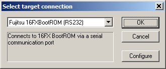 Ensure "Fujitsu 16FXBootROM (RS232)" is selected Ensure "Fujitsu 16FXBootROM (RS232)" is selected
- From the same pop up window (depicted above), click 'Configure' to bring up the RS232 configuration options. [NOTE: I find this locks my PC up for a minute or two - don't panic just wait for
the next dialogue box to appear].
- Set the communication options as depicted below - although obviously use the COM port that is correct for your host computer, which might not be COM1 as shown below!
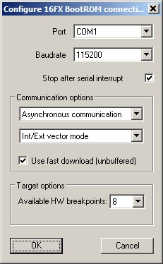 Configuring the communication parameters Configuring the communication parameters
- Select 'Open' from the EUROScope 'Communications' menu. If all is correct you should be presented with the source and assembly code ready for debugging. If not
then click the 'Initialise target and run until main' speed button. If you still cannot see the source code then use the 'Source Paths' option from the EUROScope 'Preferences'
menu to ensure EUROScope is attempting to find the source files in the correct location.
- Once a debug connection has been established EUROScope can be used to step through the code, view memory, set break points, etc as expected.
Demo Application Functionality
The demo application creates 8 co-routines, 31 persistent tasks, and periodically dynamically creates and destroys another 2 tasks. These tasks consist predominantly of the standard
demo application tasks (see the demo application section for details of the individual tasks).
The following tasks and tests are created in addition to the standard demo tasks:
- Check task
The 'check' task is responsible for ensuring that all the standard demo tasks are
executing as expected. It normally only executes every three seconds, but has the highest
priority within the system so is guaranteed to get execution time. Any errors
discovered by the check task are latched until the processor is reset. At the end
of each cycle the check task toggles an LED. The LED will toggle every 3 seconds so long as all tasks
are executing without error - the toggle rate increasing to 500ms should any task
report an error at any time [this mechanism can be tested by removing the loopback connector
while the demo is executing, and in so doing deliberately generating an error within the
'com test' tasks].
- The trace task
This task is only included in the build if INCLUDE_TraceListTasks is set to 1 within FreeRTOSConfig.h, and can only be used when executing standalone (not through the debugger).
The trace task is a user interactive task that writes execution trace and task state information to UART 1. To view the menu and provided information connect UART 1 to a terminal
program (such as Hyperterminal) on your host PC. 9600 baud is used.
The SK-16FX-EUROScope hardware contains a 2 * 7 segment numerical display, on which each segment can be controlled separately. In addition to these segments the display contains two '.'
characters that can also be controlled separately. These segments and '.' characters provide convenient outputs for the demo tasks that would normally utilise a conventional LED.
When executing correctly the demo application will behave as follows:
- The 'check' function will toggle the '.' character on the 2 * 7 segment display every 3 seconds.
- If included in the build, the trace task will send menu options to a terminal program via UART 1.
- The LED flash tasks use the segments of first character on the display - segments under control of the flash tasks will
toggle at constant rate with each task using a different frequency. Three flash tasks are created.
- The LED flash co-routines use the second character of the display. Again, each co-routine will toggle a segment
at a constant rate with each co-routine using a different frequency. Eight co-routines are created.
Optimisation
Please note that the port will not function correctly if the optimisation level is set to 0. This is because level 0 optimisation causes the compiler
to insert
prologue and epilogue instructions into the interrupt service routines used by the RTOS kernel to switch between tasks, even though the _nosavereg function qualifier is used.
If level 0 optimisation is required then
these interrupt service routines (contained within the portable layer of the RTOS kernel itself, not within the application code) will require re-writing
in pure assembly code.
Register banking
The 16FX port does not use register banking. Only bank 0 is used.
Memory model
The 16FX port can be used with small, medium, compact or large memory models. The definition configMEMMODEL within
Demo/MB96340_Softune/FreeRTOS_96348hs_SK16FX100PMC/Src/FreeRTOSConfig.h must be set to portSMALL,
portMEDIUM, portCOMPACT or portLARGE to match the project settings.
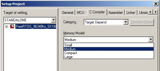 Selecting the memory model within the Softune IDE - configMEMMODEL must be
set to match the selected option Selecting the memory model within the Softune IDE - configMEMMODEL must be
set to match the selected option
Watchdog
The demo application demonstrates three methods of servicing the watchdog, these are:
- Clearing the watchdog from within the tick interrupt.
- Clearing the watchdog from within a dedicated watchdog task.
- Clearing the watchdog from within the idle task.
The settings within Demo/MB96340_Softune/FreeRTOS_96348hs_SK16FX100PMC/SRC/watchdog/watchdog.h allow the selection of the method to use.
NOTE: These three methods are provided for demonstration purposes only - all three implementations are too simple to provide a secure watchdog mechanism.
A more secure mechanism would require various system checks to be performed prior to the watchdog timer being reset.
Resources used by the RTOS
The RTOS tick is generated by reload timer 0.
The RTOS yield function uses software interrupt 122.
The RTOS yield from ISR functionality utilises the delayed interrupt.
RTOS port specific configuration
Configuration items specific to this demo are contained in Demo/MB96340_Softune/FreeRTOS_96348hs_SK16FX100PMC/Src/FreeRTOSConfig.h. The
constants defined in this file can be edited to suit your application. In particular -
- configTICK_RATE_HZ
This sets the frequency of the RTOS tick. The supplied value of 1000Hz is useful for
testing the RTOS kernel functionality but is faster than most applications require. Lowering this value will improve efficiency.
- configKERNEL_INTERRUPT_PRIORITY
This sets the interrupt priority used by the RTOS kernel.
The RTOS kernel should use a low interrupt priority (high numeric value), allowing higher priority interrupts to be unaffected by the
kernel entering critical sections. Instead of critical sections globally disabling interrupts, they only disable interrupts that
are below the RTOS kernel interrupt priority.
This permits very flexible interrupt handling:
- At the RTOS kernel priority level interrupt handling 'tasks' can be written and prioritised
as per any other task in the system. These are tasks that are woken by an interrupt. The interrupt service routine (ISR) itself should be written to be as short
as it possibly can be - it just grabs the data then wakes the high priority handler task. The ISR then returns directly into the
woken handler task - so interrupt processing is contiguous in time just as if it were all done in the ISR itself. The benefit of this is that
all interrupts remain enabled in the handler task. The Ethernet driver within the Ethernet enabled demos uses a handler task to demonstrate the mechanism.
-
ISR's running above the RTOS kernel priority are never masked out by the RTOS kernel itself, so their responsiveness is not effected by the RTOS kernel functionality.
However, such ISR's cannot use the FreeRTOS API functions. The fast timer interrupt test demonstrates this behaviour.
Each port #defines 'BaseType_t' to equal the most efficient data type for that processor. This port defines
BaseType_t to be of type short (16 bits).
Note that vPortEndScheduler() has not been implemented.
Interrupt service routines
Unlike most ports, interrupt service routines that cause a context switch have no special requirements and can be written as per the compiler documentation.
The macro portYIELD_FROM_ISR() can be used to request a context switch from within an ISR. See Demo/MB96340_Softune/FreeRTOS_96348hs_SK16FX100PMC/Src/serial/serial.c
for an example.
Switching between the pre-emptive and co-operative RTOS kernels
Set the definition configUSE_PREEMPTION within Demo/MB96340_Softune/FreeRTOS_96348hs_SK16FX100PMC/Src/FreeRTOSConfig.h to 1 to use pre-emption or 0
to use co-operative.
Compiler options
As with all the ports, it is essential that the correct compiler options are used. The best way to ensure this is to base your
application on the provided demo application project.
Memory allocation
Source/Portable/MemMang/heap_3.c is included in the demo application project to provide the memory
allocation required by the RTOS kernel.
Please refer to the Memory Management section of the API documentation for
full information.
Serial driver
Please note that the example serial driver supplied is intended to demonstrate some of the RTOS kernel features and is not intended to represent an optimal solution.
Copyright (C) Amazon Web Services, Inc. or its affiliates. All rights reserved.
|